If you want a challenge, scratch build a drone. Sounds like fun, doesn’t it? So what I thought I would do would be to do a step-by-step of building a drone, from ordering the parts, to unboxing, to assembly, to flying. So here goes.
First…find a frame you like. There are a lot of frames out there so look around. Some are fancy ($$$)…some are plain ($). But, they only look nice on the table….some look pretty cool in the air, but they’re flying fast and you’re looking through your goggles, so all you’re worried about is being able to see, and how your drone performs. The frame I am using in this build is one that popped up on Facebook one night…funny how that works….but after looking at their website, I decided to buy it. They’re great to work with and it came quickly from their store. The one I bought is called the Formula 220X Racer. The company is SpaceOneFPV, and their site is www.spaceonefpv.com. Check them out.
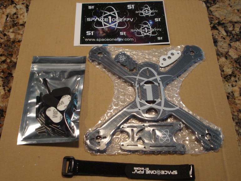
So here is what was shipped:
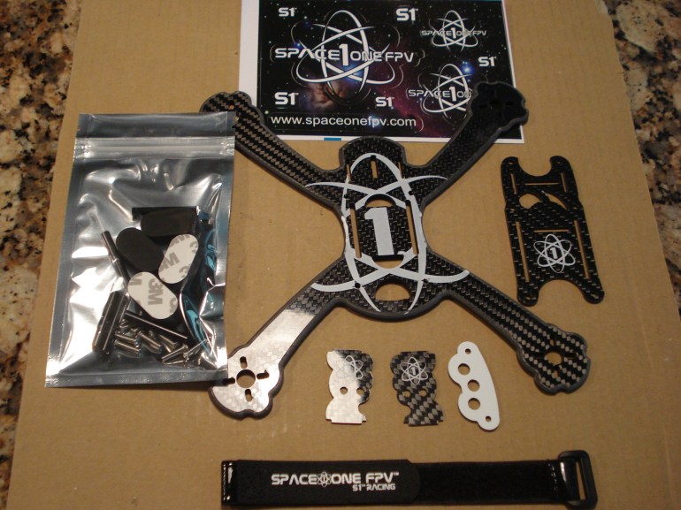
Unwrapped:
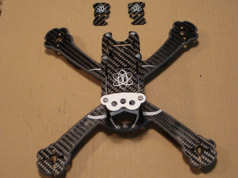
And what the frame looks like assembled:
The frame is carbon fiber and is 4.55mm thick. I think it will stand up to a lot of abuse, however time will tell. There is a lot of room for your flight control board, VTX, receiver, and camera. The frame is quite open so there will be room to layout parts prior to soldering. I’m thinking some zip ties will be handy to keep some parts secured after everything is inside the frame. The top of the frame is 35mm up from the bottom. I’m going to get some colored stand-offs to add some color to the racer.
Let the fun begin (of putting the components in).
That’s all for now. Next up will be motors/esc’s/capacitors (you want to use them)/All-in-one flight controller) soldering adventure. So stay tuned.
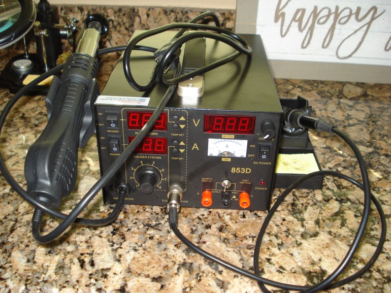
Some thoughts: You may wish to get a nice soldering station (look for picture at the bottom of this page). I’ve got one that has temperature control, which is very useful. Also, get some 63/37 solder. This is what the pros are saying you want to use. This is good for electronics. Liquid flux is good too.
One part that I bought that is really helpful is a Smoke Stopper. This little device plugs in between your battery and the battery connector. It will detect any shorts and prevent a burnout on the board…(hopefully). Several vendors sell it and it’s nice to have a confident feeling that you haven’t soldered a red wire on to the – pad on your FCB – Flight Control Board. Also, get a magnifying glass…..you’ll need it. After soldering parts to the board, inspect them….closely. Make sure your solder hasn’t flowed onto an adjacent pad. If it has, and you don’t correct it before you plug in your battery, you may smoke your board. It will happen quickly and before you can pull the plug. So, just something to keep in mind.
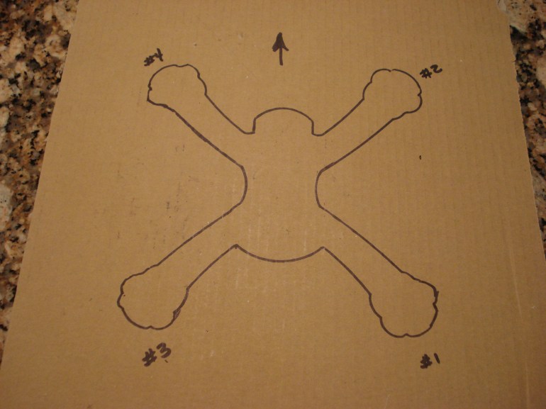
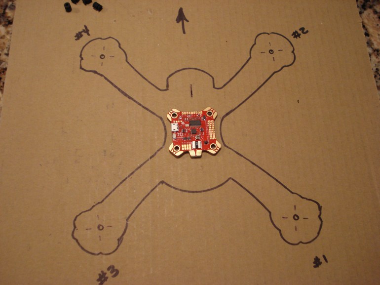
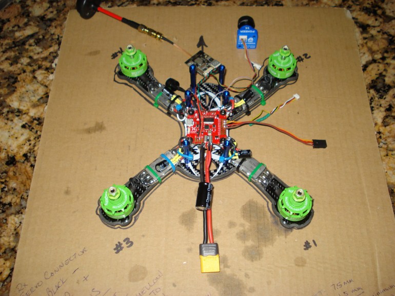
The next step for me is to outline the frame on to a piece of cardboard. This is used as a reference when I am cutting motor wires to the correct length to solder on to the ESCs, and for ESC placement and wire lengths needed to the Flight Control Board. I know…it looks like a frog. Notice the arrow….that is the front of the quad, and you’ll notice on the FCB, an arrow is stenciled on to the board…you need it pointing in the same direction.
The next thing I do is to place the FCB in the correct spot on the frame. This helps in measuring for the wire lengths needed.
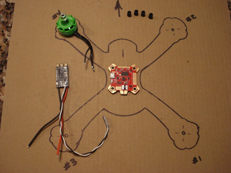
There are 4 grommets in the upper left hand corner of the photo. Those go into the four holes on the FCB. They are a pain to insert, and I’ve found that the small blade screwdriver works well in getting them started. Once started, you can pull the grommets through from the other side of the FCB. These grommets have a thick edge and a thin edge. I put the thick edge on the bottom, as I am thinking this is for vibration suppression while flying.
Cutting the wires to length and placing the ESCs where I need them is the next step in the process. The photo is self explanatory.
So, now you have placements identified; you’ve stripped the wires back and tinned them. You’ve put a solder blob on each ESC pad and they’re ready for the wires to be attached. One thing I did on this frame was to mount the FCB to the frame. What I discovered was the screw slot for the FCB was not properly located in relation to the standoffs. My FCB hit the two standoffs at the front of the board. I couldn’t mount the board as the frame was cut, so I had to drill two screw holes at the back of the frame…approximately 1/2″ back from the slot end. After I drilled the holes, I mounted the FCB and screwed the standoff in to the frame, just to be sure the FCB was located so there was no conflict with the FCB. In addition, since the board is up off the frame about 1/2″, I decided to keep the board mounted when I cut the ESC wires as they will have to be slightly longer due to the height up off the board. You may be able to notice that in the following picture.
I’ve got the motors soldered to the ESCs. I used a soldering station with the iron at 440C or 824F. What I noticed was the solder melted quickly, and flowed evenly on to the pads. I placed the wires on top of the pads (that had solder), the solder melted and the wires disappeared into the solder, and the final solder connection was bright. If it is dull, you may wish to hit it again with heat, as you may have a cold solder joint, which is not good. Another thing you’ll notice is that I put clear shrink tubing around the ESC’s…covering the solder connections from the motors and over the shrink tubing that was already on the ESC’s. This makes for a clean build and protects from dirt, etc.
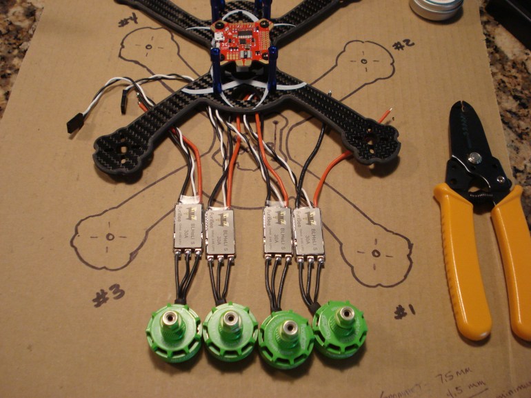
Today was a busy day. I’ve mounted the motors, and soldered the esc wires to the Flight Control Board. In addition, I made a servo connector for the receiver, and soldered it to the FCB. I guess the pizza was dripping grease while I was building…lol…actually, that is liquid flux that soaked into the cardboard.
So to the right of the quad is the receiver servo connector and Smart Port Plug (for telemetry). They are undoubtedly longer than they need to be, but this will allow the receiver to be moved around as necessary inside the frame. Also, you see the 4 wire connector next to the servo connector. For telemetry, I only need one wire..the yellow one. The other three wires have been cut to different lengths and then shrink tubing put around the wires to keep them out of the way when assembling the drone. Zip ties will be used as needed to keep all wires under the top of the frame.
If you look closely, you’ll notice at each corner there is a capacitor soldered on to the top of the ESC wires. They are 330uF – 25v capacitors, and they are there to reduce the electrical noise that is generated by the motors that could affect the video quality. I decided to do this now, because it is extremely easier to solder them now instead of later after you’ve tested the drone and discovered the video is being affected by the noise.
One thing I’ve done after each step is to verify that each solder connection is in the right place and there isn’t any solder on one pad that is touching an adjacent pad, which could cause a short and burn up the board.
Once the battery connector is soldered on, I’ll be testing everything with the smoke stop in-line with the battery to protect the board – hopefully – from any problems.
The next step will be to solder the wires on for the Video Transmitter and for the camera. Once those are done and all checks out electrically, the next step will be to program the flight control board.
Stay tuned….More to follow.
2 August 2018
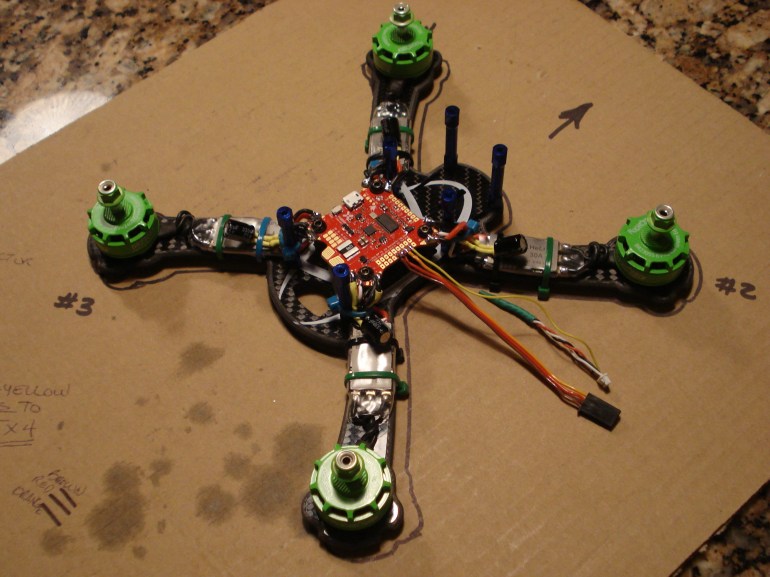
I’ve finished the build…all of the components have been soldered to the FCB. A couple things that I added to the drone and have not mentioned is that I’ve included a buzzer (to help locate the drone should it go down during a flight, hoping the battery doesn’t come loose), along with a capacitor on the battery pad (1000uF, 100v….for electrical noise reduction). Prior to putting power to the board, I went over each solder connection with a magnifying glass, and used a continuity meter to verify there were no shorts. After about a 10 minute inspection, I decided to do an initial power up. I used a 3 cell battery and put the smoke stop plug in-line. This will protect in case something has been soldered to a pad that it should not have been. IT WILL NOT PROTECT YOUR BOARD IF YOU HAVE THE MAIN POWER LEADS BACKWARDS OR YOU HAVE A BRIDGE BETWEEN THE + AND – PAD. If there is, and you plug in the battery, your board will smoke due to the short…and the board is ruined. Ok…here is the finished product. I haven’t put it together yet, but will very soon….
At the top of the drone, you’ll see the VTx (antenna connected…never power up the drone without an antenna on the VTX…if you do, you could burn out the VTx within seconds). I’ve got a blue FOXEER camera connected to the VTx with a cable that came with the camera. The frequency is set, and I have my goggles ready…and when the battery was connected, I did get a clear video signal…so that is a good sign. Also, above the battery connector, I have the 1000uF-35v capacitor soldered on top of the battery connection. This will help to reduce any motor noise in the video. Another item is a buzzer…look in the upper left corner of the drone…just down from the motor. Update…I did not see any OSD information in my goggles, specifically, Battery Voltage, RSSI, Timer and Craft Name…and that was because I didn’t solder the yellow video wire that goes from the camera to the VTx, to the FCB. That wire has to be soldered to the board to be able to use OSD from the board. I cut the wire, thus creating two ends that were soldered on to the FCB. Once I did that, OSD showed up in my goggles.
So that’s it…see it wasn’t that difficult. I know I took my time, but I was waiting for the battery connector, some new flux, and the buzzer. My next step will be to put the top on the drone after fitting the VTx, receiver, camera, buzzer and capacitor under the top of the drone. Once that is done, the next step will be to connect it to Beta Flight and set up all of the parameters for the quad (drone….quad….it means the same). I will use the same settings I have for my previous build. I’ll tell you how to quickly and easily set up the parameters for this new quad, buy copying and pasting the previous text file from my other build into this new build…..easy peasy.
Then the last step is to set up the transmitter….same method…copy a previous model, and paste it to a new model number on the transmitter…bind the receiver, and then it should…I repeat…should work. Once I know it works, then the test flight.
5 Aug 2018
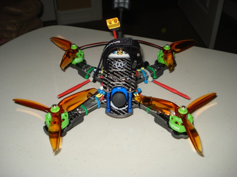
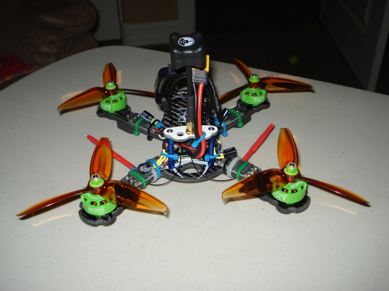
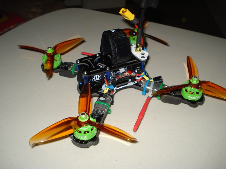
All done…the transmitter is all set up…the drone has Beta Flight set up and….it flys!!! Here are 4 shots of it…Front, back, left front, and right front. It is compact, and I filled the area up under the top of the drone.
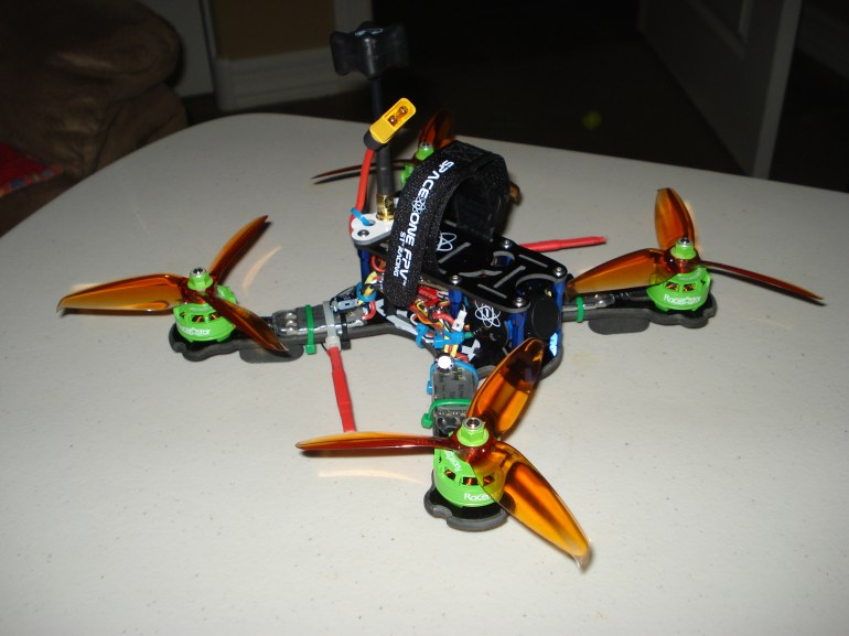
I flew it 2 times yesterday, and it is smooth and fast in the sky. I have no motor noise in the video, so that is NICE!!! I did solder the capacitors on to each ESC and the large one on to the battery connector, so I don’t know if that helped, or not….but it is easier to do it before you put it all together, than not to, and discover that you really needed them. I started out with AirMode on permanently….but I took it off because what it does is spins the props up faster so it arrests your falling rate when you throttle back (which you want), but they are spinning faster when you land…as once they spin up, there is no way to slow them down before you land. So, I like to be able to slow them down, and I’ve got Beta Flight configured such that AirMode isn’t on when I take off, but it is when I’m in ACRO mode…but when I land, it goes off. Maybe I’ll put it back on….don’t know.
I like how the drone handles, and I really like the Flight Controller…Foxeer F405 AIO board. It seems smoother…and maybe the board isn’t what is making it that way…maybe I got lucky in my selection of components. Regardless…all components are working well together.
Two of the motors were spinning the wrong direction when I was setting it up on Friday, and BLHELI32 Suite did not recognize my ESC’s so I couldn’t reverse the motors. I found another program…BLHELI Configurator in the Chrome App Store. The interface looks identical to Beta Flight, ButterFlight, CleanFlight…so it was easy to figure out. It recognized my ESC’s…and I was able to reverse the two which were spinning the wrong direction. So, I was done with configuration, and all that was left was to test fly it. I hovered it at home in my back yard so I would know that everything was working…props spinning the right direction, and that the controls moved it the correct direction. Do this before you go to the field, otherwise you may be surprised, and you could damage your drone from crashing….or you could hurt someone due to an out of control drone.
I had great RSSI strength so I wasn’t worried about losing the connection between the drone and my transmitter. The video was strong and clear. It flew fast, and was very stable. Overall, I am extremely pleased with how the build turned out. I’ve got another one in mind to build, and parts are on their way.
One last picture…I told you about the soldering station I used. Here is a picture…$70 delivered, and it really works well.
That’s all for this build. It’s been a learning experience, and if you’re getting into drones, give building one a try. It fun and satisfying.
Happy flying.
Bob
One more thing…..here is all you need to know about propellers for your Quad Copters –
