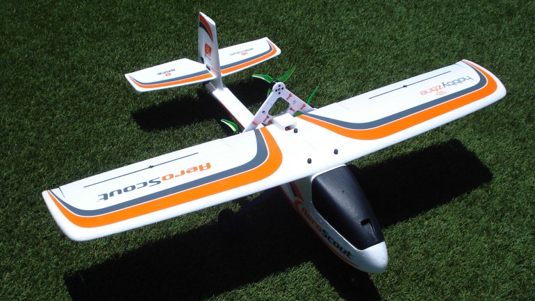
In January 2020, our club decided on a bulk purchase of the AeroScout by Hobby Zone. The decision to buy this model was made by a couple of club members after reviewing various models…and the choice was based on several factors…ease of flying, ease of construction, and overall looks of the model. Well, it was a huge hit for the club. Overall, the club bought 35 kits and we’ve been flying and racing, and just enjoying the model. Needless to say, there have been a few crashes, and mid-airs…but outside of that, they’ve survived quite nicely.
With time on my hands….and in discussion with several of the pilots, I decided to modify my AeroScout. If one motor is good, two must be better….and three…well, it just doesn’t get much better than that. So, this is about my modification to make the AeroScout a Tri-Motor plane. The first step was to design a motor mount…hmm….3 motors in a row across, or a diamond configuration. A good friend who is a wiz on the 3D printer and CAD, designed a horizontal mount for 3 motors. That configuration put the motors out a ways from the centerline of the plane….11 inches from the centerline of the left to the right motor. Also, with all three motors in-line, the thrust could be an issue when full throttle is reached…the nose generally pulls up on this model when you accelerate. So I came up with a tri-motor design, which keeps the motors closer together, and I designed the two lower motors to be 1/2 inch below the centerline of where the mount is attached to the airframe…and the third motor above…thus you have two motors pushing to raise the nose, while the upper motor pushing to lower the nose…thus hopefully offsetting each other. Also, the two lower motors are counter rotating…and the upper motor turning the same direction as the lower right motor. It didn’t appear that torque had any effect during the first two test flights. Anyway, it was a lot of fun, and I couldn’t have done it without the help of my good friend Robert…with his expertise on CAD and the 3D printer….and after several design changes, I think we’ve come up with a winner.
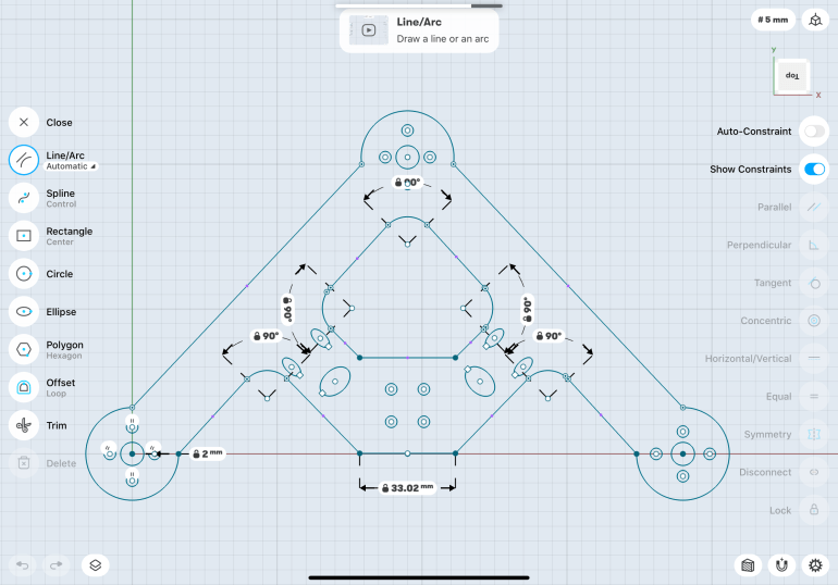
So here is the motor mount design:
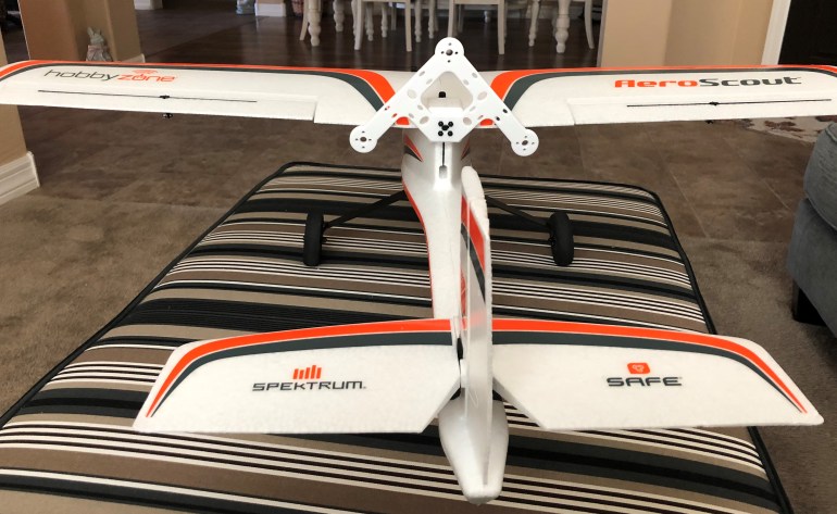
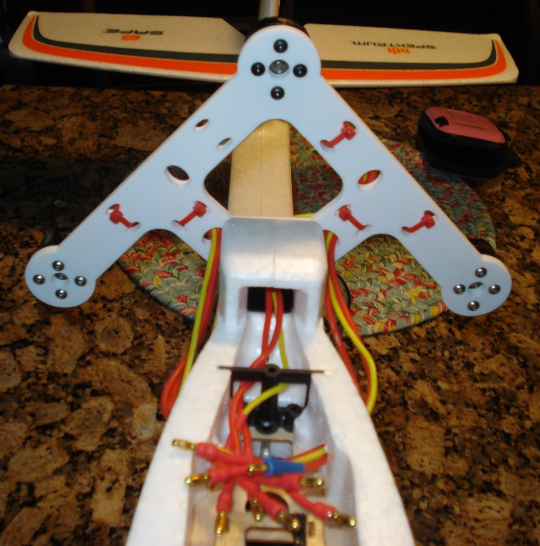
And, here it is mounted on the airframe:
So, the next step was to get the motors and determine the length needed for the wire to connect to the ESC’s, and how and where each set of wires was going to get into the fuselage. I put several layers of shrink tubing on the connections I made to the motor wires to keep them from being able to flex…if they do, you risk a wire break…and that is a pain to fix. Anyway, mine are wrapped tightly and won’t flex.
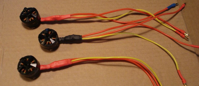
Here are the three motors after I put the wire extensions with the bullet connectors on:
As you can see below, the mount has holes where wire ties are used to secure the motor wires so they don’t vibrate during flight, and to keep them out of the way of the props while flying. Nothing worse than cutting a wire and killing a motor during a flight, or worse, on take-off. Here is how I handled that:
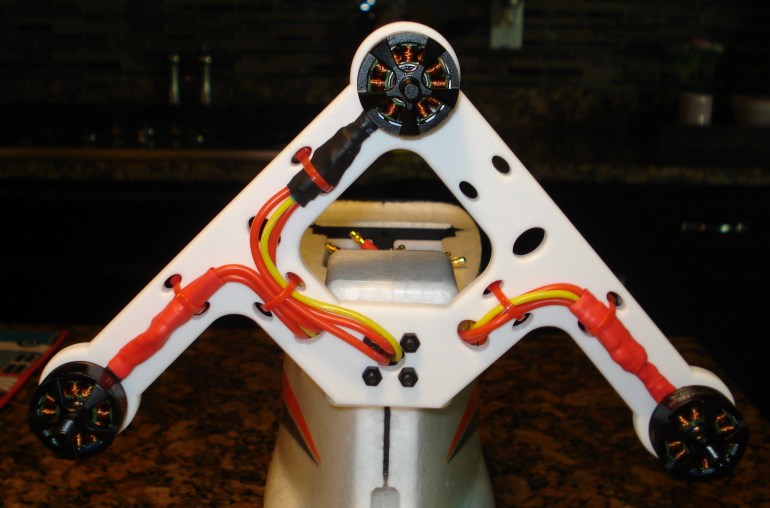
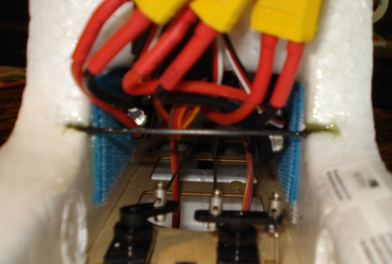
And a view looking from the front:
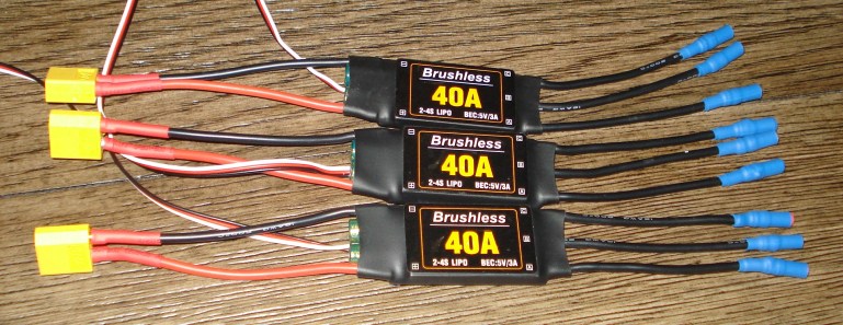
The next step was to get the ESC’s finished…soldering the battery connector and the connectors for the motors. Since I plan to run a 4S 2200mah battery, you need to have a minimum 40Amp esc for each motor. Three motors and 3 ESC’s make for a lot of wires and packing the inside of the fuselage, but more on that later.
Here are the 3 ESC’s:
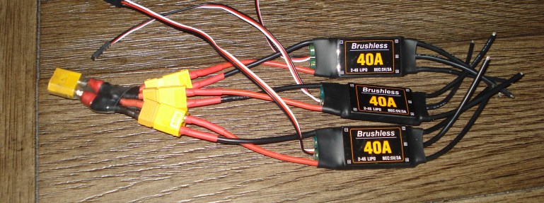
So, when you have three ESC’s, you need to have a 3-way battery connector. So, the next picture shows my homemade connector…It has some soot as I used a grill lighter to shrink the tubing…and it works perfectly. Here you go:
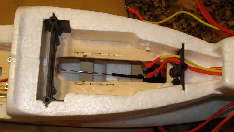
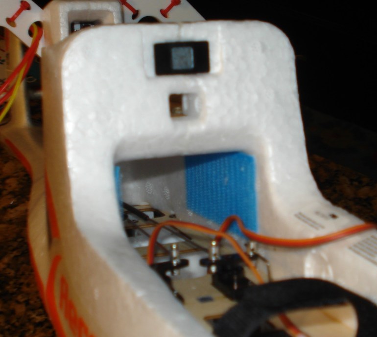
The next step is to figure out how to get all of the ESC’s and the motor wires into the fuselage, make the connections, and still have room for your receiver and the 3-way throttle connector, along with the y-connector for the ailerons. So, what I did was this….I fly Futaba, so I had a FrSky receiver, which is nice and small, and I needed to mount it lower in the fuselage, as the servo connectors are on the top of the receiver. Therefore, I cut out the raised receiver platform and opened the center portion of the plywood so I could have some room to connect the motor wires to the ESC’s.
Take a look:
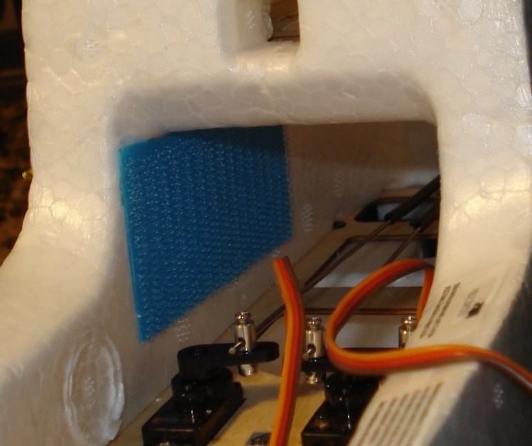
So now, how do I mount the ESC’s to the fuselage….Velcro of course:
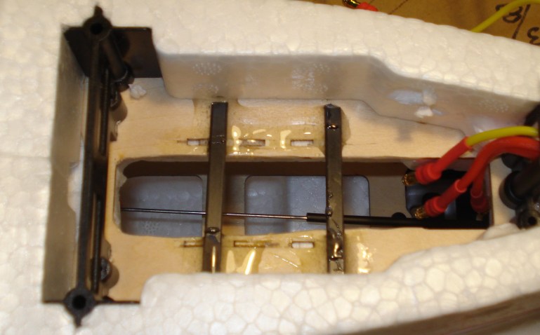
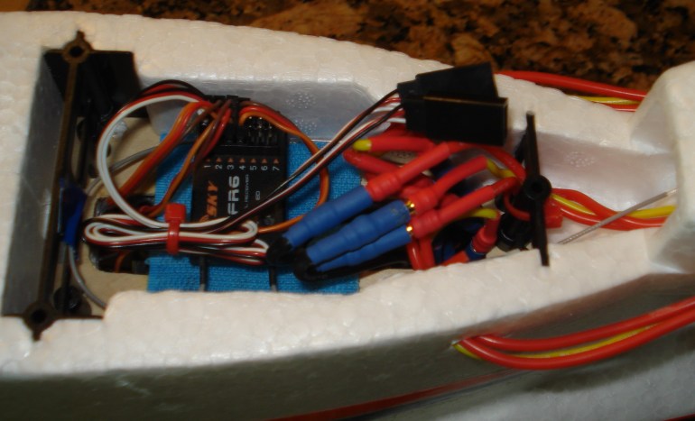
That’s good for two ESC’s….so where will #3 go? The opening where the raised area for the receiver happened to be the correct width for the ESC to be press fitted in the opening. So I added two carbon fiber rails across the opening. Take a look:
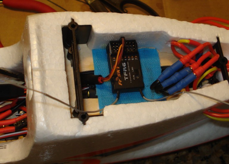
I then added Velcro to the underside and top of the rails. That way ESC will mount to the bottom and the receiver to the top. See what it looks like:

The ESC’s were installed and the receiver was mounted. Make sure you have the motors spinning the correct direction.
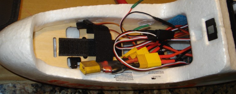
Now you get to fish all of the wires to the battery area, and up to the receiver. One thing to be sure to watch out for is keeping the wires off the servos. I put a piece of flat carbon fiber and glued it in and let the wires rest on it. So here are the pictures of the final product prior to actual flying:
Now you need to make sure that the motors are are synced up…you need to make sure all of the motors start at the same time, and run together. So, what you need to do is this…and it is a simple thing to do….each ESC has a throttle servo connector that you plug into your 3-way throttle y-connector. There are three wires on each connector, of which you only need one to be the master throttle connector. So, all you need to do is remove the center wire on two of the throttle connectors and then plug all three into the 3-way y-connector. You can cut the center wire or pull it out by lifting the black tab that holds it in position…that way, if at a later time you want to use the ESC on a separtate model, you’ll need the center wire on the throttle servo connector. So after removing the two wires, I bent the wire over, and put shrink tubing over it to keep it out of the way. That worked fine. All three motors will start up. Also, to sync the ESC’s so they will all start the motors at the same throttle position, here is what you do….with the battery disconnected, have your transmitter on; put your throttle in the full up position (full throttle), and then plug in the battery. The ESC’s will beep indicating they are in programming mode. Immediately pull the throttle back to the low throttle position. The ESC’s will beep like they normally do, and they are all synced up. Easy Peasy.
And now it is ready to fly…and it did!!! I had to add some lead to the front to help with the center of gravity…but it flew with very little trim. Landings were a dream too.

Here is a video I hope you’ll enjoy. It’s not as easy as you may think to capture the video of someone flying a plane, with a drone chasing you…..slow and steady is the right way to do it. More will be posted later as they are available (June 14, 2020).
Robert Clarke flew his drone and shot the video while I was trying to stay slow and level….enjoy the video of the first of many flights of the AeroScout Tri-Motor!!! Great editing by Robert also!!!!
Here is a list of parts I used to make my modification:
3-2400 kv drone motors (2206 or 2406 is what I’ve used)
3-5152 drone props (3 blades) or DalProp 5050…or try 2 bladed props
3-40amp ESC’s (any brand should work…make sure they support 4S batteries)
18 gauge Silicone wire – used to extend the wire leads from the motors
3.5mm bullet connectors and female connectors (for the motor leads and the ESC ends
3-way Y-connector for the throttle receiver connection (made from leftover servo connectors)
3-way connector for the battery (I made mine from batter leads from batteries I’ve discharged and discarded)
XT60 connector for both the ESC and the battery connectors
Tri-Motor mount…3D printed…not available…you’ll need to 3D print it, or make it from basswood (or some other strong wood)
Lead…for the nose to help with the balance.
3S and/or 4S batteries – 2200 mah minimum….they discharge quickly when you fly with 3 motors
Velcro
Flat carbon fiber rods
Shrink tubing
Soldering station
Flux
63/37 Solder
Good luck, have fun, and fly safely…they are really fast when you modify them…but slow nicely for easy landings….a good plane to try these modifications.
